
Published: May 12, 2026 By: Rungruang Huanraluek
What is a Surge Protector / Lightning Arrestor? How Does It Work?
In MATV, SMATV, CATV, and IPTV systems that connect to outdoor equipment such as terrestrial antennas, satellite dishes, and external signals from local cable stations, the risk of transient surges and lightning strikes is an unavoidable factor. Because coaxial cables are run externally to pull signals into the distribution system, they introduce a vulnerability to surges, lightning strikes, and even malicious electrical injections. Even if these events last for only a fraction of a second, they can instantly cause severe damage to critical hardwareranging from Headends, Receivers, Encoders, and Amplifiers down to individual television sets. This can lead to a total network crash and directly disrupt service delivery. For this reason, installing an appropriate Surge Protector / Lightning Arrestor is not just an "optional accessory" but a "fundamental component" of professional system design. This equipment acts as the primary line of defense, reducing risks and protecting the overall investment in the system. When considering that a surge protector costs only a few thousand baht but effectively prevents hundreds of thousands or even millions of baht in system damages, it represents a highly cost-effective and essential investment in engineering stability, service continuity, and long-term business security.
What is a Surge Protector / Lightning Arrestor?
A Surge Protector or Lightning Arrestor for coaxial RF lines is an inline safety component designed to block external transient overvoltages from entering the internal distribution network via coaxial cables. These power anomalies are typically triggered by nearby lightning strikes, utility power surges, electromagnetic induction, or ground loop potential differentials. Its primary role is to shield high-value equipmentincluding Headends, Receivers, Encoders/Transcoders, Amplifiers, televisions, and endpoint displaysfrom catastrophic failure caused by electrical loads that exceed operational limits.
This type of protective hardware is engineered specifically for radio frequency (RF) applications, supporting broad frequency ranges spanning from MHz to GHz bands. They feature a standard impedance rating of 75 ohms to match the structural requirements of MATV, SMATV, CATV, and IPTV networks, allowing seamless installation. Furthermore, they are manufactured with extremely low insertion loss parameters, ensuring that the device does not degrade signal levels, picture quality, or audio fidelity during normal operating conditions.
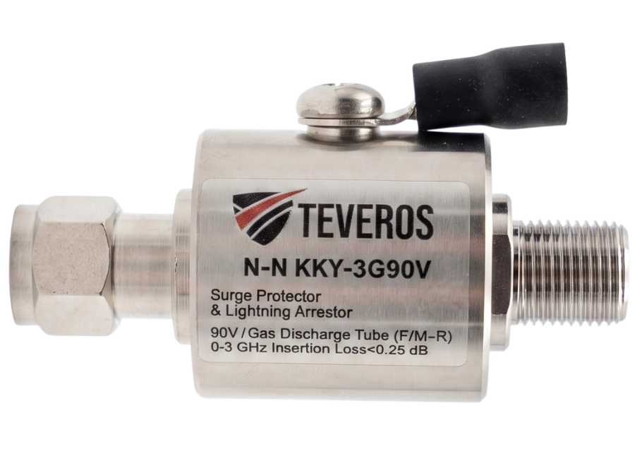
Internally, these modules typically rely on defensive components such as Gas Discharge Tubes (GDT). A GDT acts as an electrical conductor only when voltages spike past a predefined threshold, rapidly diverting excess energy away from the core line and dumping it safely into the grounding system. This disconnects the dangerous voltage path before it reaches delicate network hardware. Once the surge dissipates, the component seamlessly resets to its normal state, allowing RF signals to pass through freely. The Surge Protector / Lightning Arrestor acts as the frontline gatekeeper of an RF ecosystem, maintaining network stability, minimizing unexpected equipment failure, and maximizing uptime. While it cannot guarantee 100% protection against every direct strike scenario, it remains an indispensable asset for professional installations and a highly cost-effective safeguard against operational liability.
Where Should a Surge Protector / Lightning Arrestor Be Installed in a System?
Surge protectors should be integrated along coaxial lines at any point where there is a high probability of external overvoltage entering the network footprint. Strategic deployment zones include primary signal intake paths and immediately upstream from sensitive equipmentspecifically directly behind terrestrial antennas, inline right after LNBF feeds, at local cable drop entry lines, right before distribution amplifiers, before headend arrays or encoders, and prior to final distribution taps feeding individual television sets. Deploying shields at these specific boundaries isolates high-voltage spikes at the boundary edge, preventing them from bleeding deeper into sensitive electronic components.
Additionally, maximizing the effectiveness of a surge protector requires pairing it with an appropriately engineered, standardized grounding system. This ensures that transient energy can be channeled down into the earth quickly and safely. Installing a protective module without a proper, low-resistance ground path prevents it from functioning effectively. Therefore, selecting the correct placement along with professional grounding design is a vital requirement for long-term network security.
How Does It Work (Under Normal Conditions)?
During everyday operation, a surge protector acts purely as a passive, transparent bridge, allowing RF signals to pass through freely without causing any perceptible degradation to video or audio feeds. This transparent performance is achieved because the module is matched to the system's impedance and exhibits negligible insertion loss. Internal defense structures, like Gas Discharge Tubes (GDT), remain in an un-triggered, non-conductive state when normal electrical levels are maintained. Consequently, high-frequency signals pass directly through the core wire without experiencing any signal attenuation or interference. Under normal operating parameters, the surge protector remains completely invisible to system performance, maintaining an idle status while standing ready to react instantly if a voltage anomaly occurs.
Surge protectors should be integrated where there is a high risk of external electrical induction entering the property. Prioritizing points immediately preceding essential hardware nodessuch as directly following outdoor antenna arrays or satellite LNB dishes, before distribution amplifiers, before headends or encoders, and at final television distribution linesyields the best results. Placing them at these critical intersections alongside structured grounding networks guarantees maximum system safety.
How Does It Work During a Surge / Lightning Strike?
When a high-voltage surge or lightning strike occurs, line voltages spike exponentially, quickly exceeding the breakdown voltage limit of the surge protector's internal components. This spike instantly transitions internal components like Gas Discharge Tubes (GDT) from an insulating state to an intensely conductive path. This creates a low-resistance path that routes the destructive current down the ground wire, bypassing the primary equipment line. This conversion takes place within microseconds, successfully isolating delicate system components like headends, amplifiers, or TV tuners from devastating electrical overloads.
As soon as the transient event passes and line voltages stabilize back to normal operational parameters, the internal defensive components automatically stop conducting and instantly revert to their baseline insulating state. This allows standard RF signals to resume normal transmission across the core line without manual intervention or system downtime. Through this quick-acting mechanism, the surge protector effectively prevents component damage while preserving the overall service continuity of the network layout.
References


